
Presse universelle MecaMotion par 
Mounting and wiring of electrical hardware
Mounting the D410-2 control unit and the PM240-2 power module
The D410-2 control unit is mounted directly on the PM240-2 power module, as shown in figure 1.

Figure 1: Mounting of D410-2 on the PM240-2
The PM240-2 power section is fixed directly to the mounting plate of the electrical cabinet using three M4 screws. The system shielding kit is attached to the PM240-2. (see figure 2 below)
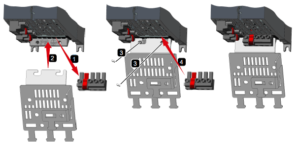
Figure 2: Mounting the shielding kit on PM240-2
The dimensions of the power module are given in table 1 and illustrated in figure 3.
Frame size |
Width [mm] |
Height without shield plate [mm] |
Height with shield plate [mm] |
Depth without D410-2 [mm] |
Depth with D410-2 [mm] |
|---|---|---|---|---|---|
FSA |
73 |
196 |
276 |
165 |
240 |
FSB |
100 |
292 |
370 |
165 |
240 |
FSC |
140 |
355 |
432 |
165 |
240 |
Table 1: PM240-2 dimensions
The drilling dimensions of the power module are given in table 2 and illustrated in figure 3.
Frame size
|
Drilling dimensions [mm] |
||
|---|---|---|---|
h |
b |
c |
|
FSA |
186 |
62.3 |
6 |
FSB |
281 |
80 |
6 |
FSC |
343 |
120 |
6 |
Table 2: Drilling dimension
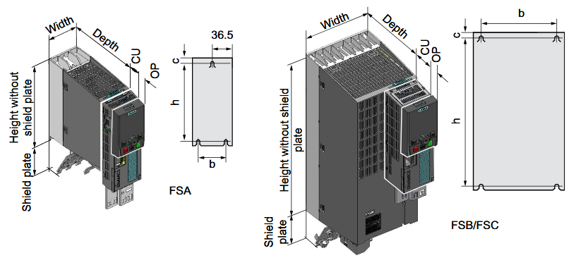
Figure 3: Power module dimensions and drilling dimensions
Be careful, the power module should only be installed in the vertical position with the motor connectors at the bottom.
For the cooling of the power module to be carried out correctly, it is necessary to provide air clearance at the top, bottom and front.
Frame size
|
Cooling air clearances [mm] |
||
|---|---|---|---|
Top |
Bottom |
Front |
|
FSA |
80 |
100 |
100 |
FSB |
80 |
100 |
100 |
FSC |
80 |
100 |
100 |
Table 3: Cooling air clearances
Electrical wiring
For wiring the PM240-2 power module and the D410-2 control unit, refer to the document "Universal presse block diagram"
