
Presse universelle MecaMotion par 
Control the press by a PLC
The press can be controlled by a PLC via a PROFINET connection.
Be careful, you must first set the "communication" parameter to Profinet in MecaMotion.
Press PROFINET inputs
In the table below, you will find all the commands that the press can receive via the PROFINET link.
N° |
Direction (from the press) |
Description |
PROFINET address |
Format |
|---|---|---|---|---|
1 |
IN |
Program number to be activated |
224 |
BYTE |
2 |
IN |
Operating mode to be activated |
225 |
BYTE |
3 |
IN |
Position setpoint for manual positioning[mm] |
226 |
REAL |
4 |
IN |
Speed setpoint for manual positioning [mm/s] |
230 |
REAL |
5 |
IN |
Acc./Dec. setpoint for manual positioning [mm/s2] |
234 |
REAL |
6 |
IN |
Range of the force sensor to be activated |
238 |
BYTE |
7 |
IN |
Start the actual program |
239.0 |
BIT |
8 |
IN |
Going down in JOG (run on sight) |
239.1 |
BIT |
9 |
IN |
Going up in JOG (run on sight) |
239.2 |
BIT |
10 |
IN |
Manual positioning mode, absolute or relative (absolute = 0) |
239.3 |
BIT |
11 |
IN |
Start manual positioning |
239.4 |
BIT |
12 |
IN |
Reset the force sensor |
239.5 |
BIT |
13 |
IN |
Acknowledge present errors |
239.6 |
BIT |
14 |
IN |
Change the operating mode |
239.7 |
BIT |
15 |
IN |
|
240.0 |
BIT |
16 |
IN |
Validate the part program number |
240.1 |
BIT |
17 |
IN |
Enable breakpoints in automatic mode (if = 0, breakpoints not used) |
240.2 |
BIT |
18 |
IN |
Continue the program execution after breakpoint |
240.3 |
BIT |
19 |
IN |
Go to release position |
240.4 |
BIT |
20 |
IN |
Go to initial position |
240.5 |
BIT |
21 |
IN |
Validate envelope (number + decoding) |
240.6 |
BIT |
22 |
IN |
Enable envelope (active =1 inactive =0) |
240.7 |
BIT |
23 |
IN |
Envelope number to be activated (0 = no envelope) |
241 |
BYTE |
24 |
IN |
Stop axis movement |
242.0 |
BIT |
25 |
IN |
Continue axis movement |
242.1 |
BIT |
Table 1: PROFINET commands
PROFINET press outputs
In the table below, you will find all the information that the press can send back to the PLC via the PROFINET link
N° |
Direction (from the press) |
Description |
PROFINET address |
Format |
|---|---|---|---|---|
1 |
OUT |
Actual program number |
224 |
BYTE |
2 |
OUT |
Actual press mode |
225 |
BYTE |
3 |
OUT |
Actual range of the force sensor |
226 |
BYTE |
4 |
OUT |
|
227 |
BYTE |
5 |
OUT |
Actual position[mm] |
228 |
REAL |
6 |
OUT |
Actual speed [mm/s] |
232 |
REAL |
7 |
OUT |
Actual measuring sensor value (option) [mm] |
236 |
REAL |
8 |
OUT |
Actual value of the force sensor [N] |
240 |
REAL |
9 |
OUT |
Actual program running |
244.0 |
BIT |
10 |
OUT |
Program finished |
244.1 |
BIT |
11 |
OUT |
|
244.2 |
BIT |
12 |
OUT |
Actual manual positioning mode, absolute or relative (absolute = 0) |
244.3 |
BIT |
13 |
OUT |
Manual position reached |
244.4 |
BIT |
14 |
OUT |
Error present |
244.5 |
BIT |
15 |
OUT |
Initial position reached |
244.6 |
BIT |
16 |
OUT |
Program stopped on breakpoint |
244.7 |
BIT |
17 |
OUT |
Axis enabled (unlocked) |
245.0 |
BIT |
18 |
OUT |
Presse cpu started (power up) |
245.1 |
BIT |
19 |
OUT |
Stopwatch 1 in progress |
245.2 |
BIT |
20 |
OUT |
Stopwatch 2 in progress |
245.3 |
BIT |
21 |
OUT |
Stopwatch 3 in progress |
245.4 |
BIT |
22 |
OUT |
Stopwatch 4 in progress |
245.5 |
BIT |
23 |
OUT |
Stopwatch 5 in progress |
245.6 |
BIT |
24 |
OUT |
|
245.7 |
BIT |
25 |
OUT |
Errors see "PROFINET error list", |
246.0 à 250.7 |
BIT |
26 |
OUT |
Actual envelope number |
251 |
BYTE |
27 |
OUT |
Release position reached |
252.0 |
BIT |
Table 2: Informations returned by PROFINET
Explanation and examples to use the different PROFINET input/output signals with the press
Power on press
When the press is switched on, you must wait until output bit n°245.1 (press cpu started) is at "1" to send commands or read the information.
Acknowledgement of errors
To acknowledge the errors, you must set input bit n°239.6 for 50 ms.
Then, you can check that no errors are present using output bit n°244.5. (if they are an error present, the bit is "1")
Changing the operating mode
There are 2 different operating modes. To change mode, byte n°225 ("Operating mode to be activated") must take one of the values below:
•Byte n°225 = 16#01:
| Value to past the press in "manual mode". In this mode, it is possible to control the press in run on sight (JOG +/-).It is also possible to perform manual positioning by giving a relative or absolute position setpoint. |
•Byte N°225 = 16#02:
| Value to past the press into "automatic mode". This mode allows you to execute the various part-programs. |
To change the press mode, you must send one of the values described above in input byte 225, wait 50 ms, then set input bit 239.7 to "1" for 50 ms to confirm the mode change. You can then see if the actuel press mode has been changed using the output byte n°225. (see figure 1 below)
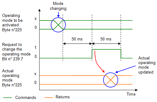
Figure 1: Chronogram of mode changing
Manual positioning
As explained above, in order to be able to perform manual positioning, the press must be in manual mode.
First, you must update the "positioning" data above:
•Position [mm] (REAL input n°226)
•Velocity [mm/s] (REAL input n°230)
•Acceleration / deceleration [mm/s2] (REAL input n°234)
•Positioning mode "Absolute" (bit input n°239.3 = "0") or "Relative" (bit input n°239.3 = "1").
These parameters will be taken into account by the press when it receives the " Start manual positioning" signal (Bit n°239.4).
As soon as the positioning is completed, output bit n°244.4 (manual position reached) will be set to "1". You can then reset the bit "start manual positioning"
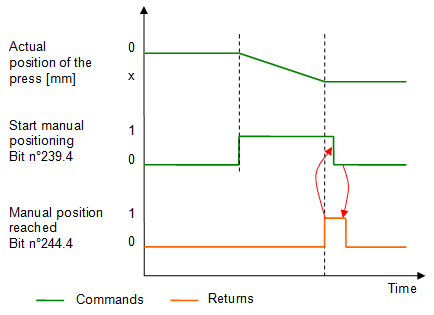
Figure 2: Starting manual positioning
Run on sight (JOG)
To control the press in run on sight (JOG mode), first, it is necessary to activate the manual mode and enter a speed in [mm/s] in output Real n°230.
Bit n°239.1 (JOG+) allows to go down and bit n°239.2 (JOG-) allows to go up.
These bits must be held at "1" for movement to occur, when they past to "0" the press stops.
Go to the initial position
To go to the initial position, you must set bit n°240.5. The press will then move and when the initial position is reached, the output bit n°244.6 will set to "1", you can then reset the control bit n°240.5. (see figure 3).
The initial position of the press is a default parameter to be entered in MécaMotion.
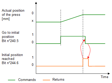
Figure 3: Chronogram to go to the initial position
Go to the release position
To go to the release position, you must set bit n°240.4. The press will then move and when the release position is reached the output bit n°252.0 will set to "1", you can then reset the control bit n°240.4 to "0". (see figure 4).
The press release position is a default parameter to be entered in MecaMotion.
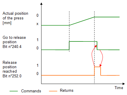
Figure 4: Chronogram to go to the release position
Activating a program number
To be able to activate a program number, there must be no program running (output bit n°244.0 must be at "0").
If this is the case, you must send the number of the program to be activated to input byte n°224, wait 50 ms, then validate this number by setting input bit n°240.1 for 50 ms.
When the active part program number is updated in output byte n°224, it means that the change has been made, you can then start the actual program using input bit n°239.0.
If the return of the active program number (output byte n°224) does not update, check that no errors are present.
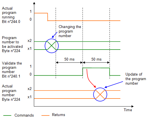
Figure 5: Chronogram activation of a program number
Activating an envelope number
To activate an envelope, you must send its number to input byte n°241, wait 50 ms, then validate this number by activating input bit n°240.6 for 50 ms. When the active envelope number is updated in output byte n°251, it means that the change has been made.
If the number of the active envelope does not update, check that no errors are present (output bit n°244.5).
Important, you can choose at any time to work with or without the envelope using bit n°240.7. This bit must be at "1" to work with the envelope.

Figure 6: Chronogram activation of an envelope number
Starting a program
Before starting a program, you must make sure that no errors are present (output bit n°244.5 at "0"), that the program is not running (output bit n°244.0 at "0") and that the press is in automatic mode (output byte n°225 = 16#02).
If the above conditions are met, you can start the actual program by setting input bit n°239.0, this bit must be maintained at "1" until the program execution is completed (output bit n°244.1 switches to "1"). When you have the information that the program is finished or that an error is present, you can set the program start command to "0" (input bit n°239.0).
If an error is present, you must set the error acknowledgement bit n°239.6.
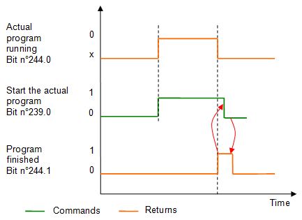
Figure 7: Chronogram starting the actual program
Using the force sensor in manual mode
In manual mode, if you want to reset the force sensor value to zero, you must set input bit n°239.5 for 200 ms.
To select the range of the force sensor, you must set bit n°239.5 to "1" (force sensor in reset mode), wait 50 ms, send the number of the range chosen in input byte n°238, wait 50 ms and then set bit n°239.5 to "0" to switch the force sensor to measurement mode.
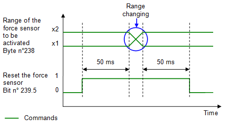
Figure 8: Chronogram change of force sensor range
Currently, there are 2 possible ranges:
•Range 1 (small range), the value to be transferred to the byte is "1".
•Range 2 (large range), the value to be transferred to the byte is "2".
You can view the active range of the force sensor, using output byte 226.
Stopping the axis movement
At any time, and independently of the active mode, you can stop the axis movement using the input bit n°242.0. You can then resume the movement using input bit n°242.1. If a part-program was running at the time of stopping, it is paused and if you restart the movement of the axis, program execution resumes.
Program stop with instruction break point
When a break point instruction is present in the active program, you have the choice to do the break or not. This choice is made with input bit n°240.2 to be set to "1" if you want to make the breaks.
When the program execution is paused, you must set input bit 240.3 for 50 ms to continue the execution.
Stopwatchs
When you use the stopwatch instruction in a program, you can view the stopwatches that are currently being scrolled via PROFINET.
Up to 5 stopwatches can be programmed.
Below is the list of bit addresses to view the stopwatches currently running:
•Stopwatch 1: Output bit n°245.2
•Stopwatch 2: Output bit n°245.3
•Stopwatch 3: Output bit n°245.4
•Stopwatch 4: Output bit n°245.5
•Stopwatch 5: Output bit n°245.6
Viewing press data
It is possible to visualize the position, speed and force of the press in real time.
Actual position of the press [mm]: REAL output n°228
Actual speed of the press [mm/s]: REAL output n°232
Actual measuring sensor value [mm]: REAL output n°236 (option)
Actual value of the force sensor [N]: REAL output n°240
