
Presse universelle MecaMotion par 
PROFINET press control FB
To facilitate the control of the press from a PLC, we have developed a function block (FB_MecaMotion_press).
This one includes all PROFINET inputs and outputs required to control the press.
List of block inputs and outputs
Variable name |
Declaration |
Type of data |
Description |
|---|---|---|---|
Hardware_identifier_press_inputs |
INPUT |
HW_IO |
Hardware identifier of the PROFINET inputs |
Hardware_identifier_press_outputs |
INPUT |
HW_IO |
Hardware identifier of the PROFINET outputs |
Ack_error |
INPUT |
BOOL |
Acknowledge present errors (Rising edge detection) |
Operating_mode |
INPUT |
BYTE |
Operating mode to be activated (Manual = 1, Automatic = 2) |
Manual_positioning_relative_mode |
INPUT |
BOOL |
Manual positioning mode (Absolute = 0, Relative = 1) |
Manual_position |
INPUT |
REAL |
Position setpoint for manual positioning[mm] |
Manual_speed |
INPUT |
REAL |
Speed setpoint for manual positioning [mm/s] |
Manual_acceleration_deceleration |
INPUT |
REAL |
Acceleration/deceleration setpoint for manual positioning[mm/s²] |
Start_manual_positioning |
INPUT |
BOOL |
Start manual positioning (This input must be kept at "1" until the "Manual_position_reached" output is active) |
Jog_downwards |
INPUT |
BOOL |
Run on sight, the press goes down as long as the input is active (Manual Mode) |
Jog_upwards |
INPUT |
BOOL |
Run on sight, the press goes up as long as the input is active (Manual Mode) |
Go_to_initial_position |
INPUT |
BOOL |
Go to the initial position entered in the press parameters from MecaMotion |
Go_to_release_position |
INPUT |
BOOL |
Go to the release position entered in the press parameters from MecaMotion |
Stop_movement |
INPUT |
BOOL |
Stop the axis movement (manual or automatic mode) and pause the execution of the part program (Rising edge detection) |
Continue_movement |
INPUT |
BOOL |
Resume the axis movement (manual or automatic mode) and continue executing the part-program (Rising edge detection) |
Reset_force_sensor |
INPUT |
BOOL |
Reset the force sensor, the input must be "1" for the reset to take place (Rising edge detection) (Manual mode) |
Force_sensor_range |
INPUT |
BYTE |
Choice of force sensor range (1 = small range, 2 = large range) The force sensor automatically switches to "reset" mode each time the range is changed (Manual Mode) |
Program_number |
INPUT |
BYTE |
Program number to be activated (from 1 to 253) (Program activation is done as soon as the value of the input is modified) |
Envelope_number |
INPUT |
BYTE |
Envelope number to be activated (from 1 to 253) (The decoding of the envelope is done as soon as the value of the input is modified) |
Envelope_monitoring |
INPUT |
BOOL |
Enable or disable envelope control (The input must be set to "1" for the control to be active) |
Start_program |
INPUT |
BOOL |
Start the execution of the program. (This input must be kept at "1" until the "Program_finished" or "Error" output is active) |
Enable_break_points |
INPUT |
BOOL |
Enable breakpoints (The input must remain active to make breaks at the breakpoints) |
Continue_after_break_point |
INPUT |
BOOL |
Continue after breakpoint (Rising edge detection) |
DB_setpoints_results |
INPUT |
DB_ANY |
Data block containing the user variables that allow setpoints to be sent and results to be received |
Error |
OUTPUT |
BOOL |
At least one error is present if this output is "true". |
Message |
OUTPUT |
BOOL |
At least one message is present if this output is "true". |
Axis_enabled |
OUTPUT |
BOOL |
When this output is at "1" the press is ready to work |
Press_cpu_started |
OUTPUT |
BOOL |
When you turn on the press, wait until this output changes to "1" before sending a command. |
Actual_operating_mode |
OUTPUT |
BYTE |
Actual operating mode (Manual = 1, Automatic = 2) |
Manual_positioning_relative_mode_active |
OUTPUT |
BOOL |
Actual manual positioning mode (Absolute = 0, Relative = 1) |
Manual_position_reached |
OUTPUT |
BOOL |
This output is activated when the manual position is reached |
Initial_position_reached |
OUTPUT |
BOOL |
This output is activated when the axis has reached the initial position |
Release_position_reached |
OUTPUT |
BOOL |
This output is activated when the axis has reached the release position |
Force_sensor_actual_range |
OUTPUT |
BYTE |
Actual force sensor range (1 = small range, 2 = large range) |
Actual_program_number |
OUTPUT |
BYTE |
Actual program number (from 1 to 253) |
Program_running |
OUTPUT |
BOOL |
This output is activated when the program is running |
Program_finished |
OUTPUT |
BOOL |
This output is activated when the program execution is finished. |
Actual_envelope_number |
OUTPUT |
BYTE |
Actual envelope number (from 1 to 253) |
Stopwatch_1_running |
OUTPUT |
BOOL |
Stopwatch 1 is running when the output is at "1". |
Stopwatch_2_running |
OUTPUT |
BOOL |
Stopwatch 2 is running when the output is at "1". |
Stopwatch_3_running |
OUTPUT |
BOOL |
Stopwatch 3 is running when the output is at "1". |
Stopwatch_4_running |
OUTPUT |
BOOL |
Stopwatch 4 is running when the output is at "1". |
Stopwatch_5_running |
OUTPUT |
BOOL |
Stopwatch 5 is running when the output is at "1". |
Program_on_break_point |
OUTPUT |
BOOL |
The program is stopped at a breakpoint when this output is at "1". |
Actual_position |
OUTPUT |
REAL |
Actual axis position in[mm] |
Actual_speed |
OUTPUT |
REAL |
Actual axis speed setpoint in[mm/s] |
Actual_measuring_sensor_value |
OUTPUT |
REAL |
Actual measuring sensor value in[mm] |
Actual_force |
OUTPUT |
REAL |
Actual force value[N] |
Errors_messages |
OUTPUT |
Struct of 120 Bool |
Errors and messages |
Table 1: Designation of the inputs/outputs of the block
Siemens PLC
On the "Hardware_identifier_presse_inputs" and "Hardware_identifier_presse_outputs" inputs, you must give the hardware identifier of the Profinet input and output range in decimal format.
When using a Siemens PLC, you must use a data block to write/read user variables. This block must have the following structure and must be transferred to the "DB_setpoints_results" input.
Structure of the setpoints / results DB:
Type |
Start address |
Size and format |
Description |
|---|---|---|---|
Setpoint |
0.0 |
50 DWORD |
User input variables of type DINT or REAL |
Setpoint |
200.0 |
32 BOOL |
User input variables of type BOOL |
Setpoint |
204.0 |
5 DWORD |
Reserve |
Result |
224.0 |
50 DWORD |
User output variables of type DINT or REAL |
Result |
424.0 |
32 BOOL |
User output variables of type BOOL |
Result |
428.0 |
5 DWORD |
Reserve |
Table 2: Structure of the setpoint / result data block under Siemens
Beckhoff PLC
In the FB "MecaMotion Press" for Beckhoff PLCs, the declaration of the Profinet input and output ranges is done via 2 Bytes tables of length 254.
When using a Beckhoff PLC, user variables are written/read via tables.
Type |
Size and format of the table |
Description |
|---|---|---|
Setpoint |
50 DWORD |
User input variables of type DINT or REAL |
Setpoint |
32 BOOL |
User input variables of type BOOL |
Result |
50 DWORD |
User output variables of type DINT or REAL |
Result |
32 BOOL |
User output variables of type BOOL |
Table 3: Setpoints/results tables with Beckhoff PLC
FB errors
In addition to the Profinet press errors listed in the "PROFINET error list" topic, the errors below may appear, these errors are part of the Boolean structure of the "Errors_messages" output. If you use a Siemens PLC, the structure must have 120 Booleans.
Error n° |
Type |
Error description |
Format |
|---|---|---|---|
80 |
Error |
Press not started (The press is starting) |
BOOL |
81 |
Error |
Manual mode not active (manual controls cannot be used) |
BOOL |
82 |
Error |
Program number or envelope number not active at program start (setpoint different from return) |
BOOL |
Table 4: Internal errors in the functional block
Error acknowledgement
To acknowledge the errors, you must set the "Ack_error" input to "1". (Rising edge detection)
Operating mode changing
There are 2 possible operating modes, manual = 1 or automatic = 2.
To activate one of these modes, you must write one of the values listed above in the "Operating_mode" input byte. You can then check that the mode has been activated, using the output byte "Actual_operating_mode".
Positionnement manuel
To perform manual positioning, you must enter the following input parameters:
•Manual_positioning_relative_mode (absolute=0, relative=1)
•Manual_position (position setpoint [mm])
•Manual_speed (speed setpoint [mm/s])
•Manual_acceleration_deceleration (acceleration and deceleration setpoint [mm/s2])
Once these parameters have been entered, you can start positioning using the "Start_manual_positioning" input, this input must be maintained to "1" until the "Manual_position_reached" output becomes true. Then, when you reset the "start" input, the output "Manual_position_reached" becomes false too. You can then perform a new positioning.
Run on sight (JOG)
The "Jog_downwards" and "Jog_upwards" inputs are used to move axis in run on sight. As long as the input is true, the axis moves, otherwise it stops.
Be careful, you must enter a speed in the "Manual_speed" input parameter for the movement to take place.
Position initiale et position de dégagement
Go to the initial position (manual or automatic mode): The "Go_to_initial_position" input allow to move axis to the initial position entered in the parameters from MecaMotion. This input must be maintained to "1" until the "Initial_position_reached" output becomes true. It means that the positioning is finished, you can then reset the input and the output will also reset.
Go to the release position (manual or automatic mode): The "Go_to_release_position" input allow to move axis to the release position entered in the parameters from MecaMotion. This input must be maintained to "1" until the "Release_position_reached" output becomes true. It means that the positioning is finished, you can then reset the input and the output will also reset.
Stop movement
In manual or automatic mode, when a rising edge is detected on the "Stop_movement" input, the axis stops and the program execution is paused.
Movement resumption
The resumption of axis movement and program execution takes place when a rising edge is detected on the "Continue_movement" input. (Manual or automatic mode)
Force sensor management
To reset the force sensor, you must set the "Reset_force_sensor" input to "1". The reset is performed for 200[ms] after detecting a rising edge on the input.
To change the range of the force sensor, you must enter the number of the range you want to activate in the "Force_sensor_range" input byte. When you change the range of the force sensor, it is reset for 500[ms].
Program changing
To activate a program, simply enter its number in the "Program_number" input byte. You can then check whether the program has been activated using the "Actual_program_number" output.
Starting the actual program
To start the actual program, the "Program_running" and "Error" outputs must be "false". Then you must activate the "Start_program" input and keep it active until the "Program_finished" output becomes true. When the program is finished, you can reset the "Start_program" input and the "Program_finished" output will also be reset. You can then restart the program.
Envelope changing
To select and activate an envelope, you must enter its number in the "Envelope_number" input byte. You can check that the selected envelope has been activated using the output byte "Actual_envelope_number".
You can activate or deactivate the envelope control at any time using the "Envelope_monitoring" input. This input must be set to "1" for the control to be active.
Break points
If you use the breakpoint instruction in your program, you have the choice to make or not the break during program execution.
To activate the breakpoints you must set the "Enable_breakpoints" input to "1". When the program execution is stopped at a breakpoint, the output "Program_on_breakpoint" changes to "1". You can continue running the program by activating the "Continue_after_breakpoint" input (rising edge detection).
Stopwatches
If you use the stopwatch instruction in your program, you can view the running stopwatches at any time using the "Stopwatch_..._running" outputs.
Press technology data
You can view at any time the position and speed of the axis, the measuring sensor value and the force value using the following outputs:
•"Actual_position" [mm] REAL Format
•"Actual_speed" [mm/s] REAL Format
•"Actual_measuring_sensor_value" [mm] (option) REAL Format
•"Actual_force" [N] REAL Format
Example of use of the press control FB: We would like to insert a rivet. 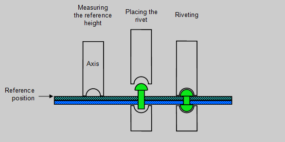 Figure 1: Insertion of a rivet To do this, we use two programs created in MecaMotion (Programming and press configuration software). The first program measures the reference height that will be used to determine the final insertion position. In this one (Figure 2), the reference height is measured using the "position measurement" function. This function can be used when the press is equipped with a precision switch. The measured position will allow you to determine the insertion position of the rivet. The position measurement function must always be located before a positioning, it is during this one that the measurement is performed. In this positioning, you must set a position that cannot be reached (lower than the reference), the axis will be stopped when the precision switch is switched by the "position measurement" function. Before executing this program, you must send the setpoints "reference pre-position" and "unreachable position" to the press via PROFINET. When the cycle is finished, the press returns by PROFINET, the maximum force measured during detection and the reference position. 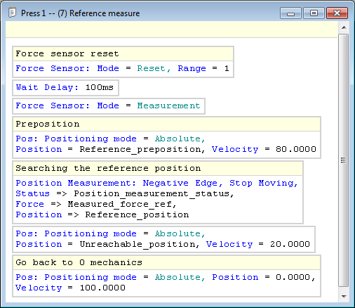 Figure 2: MecaMotion Program - Reference Measurement The second program allows the rivet to be inserted, this insertion is done in position. The actual insertion position is calculated as follows: "actual insertion position" = "reference position" + "precision switch stroke" - "insertion height" Before starting the program, you must give the following setpoints by PROFINET: •Preposition (Position up to which the press descends at high speed) •Switch stroke (Precision switch stroke) •Insertion height (desired insertion height compared to the reference) •Insertion speed (descent speed during insertion) When insertion is complete, the maximum force measured during the cycle is returned by PROFINET.  Figure 3: MecaMotion program - Rivet insertion After having carried out the two programs, you must associate in the PLC and MecaMotion the PROFINET variables used to give the setpoints and receive the results. In Figure 4 below, you must declare all the setpoints that will have to be sent to the PLC. It is essential to enter the start address of the Profinet input/output variables (they must be the same as those configured in the PLC).  Figure 4: Association of setpoint variables to PROFINET variables from Mecamotion In Figure 5 below, you associate all the result variables that will be returned to the PLC. 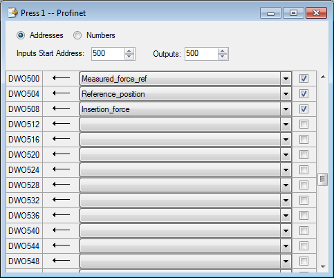 Figure 5: Association of result variables to PROFINET variables from MecaMotion When the programs are created and the input/output variables are declared in MecaMotion, you must, in the PLC programming platform, call the FB and assign all its inputs/outputs. These are all detailed in the block commentary. Then, you must perform the programming below: •Send the setpoints and read the results to the PROFINET addresses configured in MecaMotion. •Enable automatic mode: To activate automatic mode, you must check that the "Press_cpu_started" output is active and then you must set the value 2 in the "Mode" input to activate automatic mode. You can then check that the mode has been activated using the "Actual_operating_mode" output. •Select the program number and start it.
Once you have completed all the above steps, all you have to do is run the "reference_measurement" program and then the "rivet_insertion" program. |
