
Presse universelle MecaMotion par 
Association of user variables to physical inputs/outputs
It is possible to associate user variables (variables that are used in part programs) to physical inputs or outputs of the D410-2 control unit.
In Table 1, you find all the digital inputs and outputs of the D410-2 control unit that can be used to send or receive signals from outside.
Direction (from the press) |
Input/Output number |
Physical terminal |
Format of the associated variable |
|---|---|---|---|
IN |
DI0 |
X121.1 |
BOOL |
IN |
DI1 |
X121.2 |
BOOL |
IN |
DI2 |
X121.3 |
BOOL |
IN |
DI8 |
X121.7 |
BOOL |
IN |
DI9 |
X121.8 |
BOOL |
OUT |
DO10 |
X121.10 |
BOOL |
OUT |
DO11 |
X121.11 |
BOOL |
OUT |
DO15 |
X131.5 |
BOOL |
IN |
DI18 |
X120.6 |
BOOL |
IN |
DI19 |
X120.7 |
BOOL |
IN |
DI20 |
X120.9 |
BOOL |
IN |
DI21 |
X120.10 |
BOOL |
IN |
DI22 |
X121.1 |
BOOL |
Table 1: List of physical inputs/outputs that can be used on the D410-2
In addition to these Boolean inputs/outputs, there are three other inputs that can be associated to variables. These inputs are of LREAL type and must be associated to variables of the same type.
Direction (from the press) |
Input/Output number |
Physical terminal |
Format of the associated variable |
|---|---|---|---|
IN |
Actual measuring sensor position value |
-- |
LREAL |
IN |
Actual force value |
-- |
LREAL |
IN |
Actual axis position |
-- |
LREAL |
Table 2: List of LREAL inputs
The inputs "Actual measuring sensor position" and "Actual force value" are inputs that are already connected to the measuring sensor and the force sensor respectively. The "Actual axis position" input is not a physical input, but an internal value of the control unit.
When associated to a variable, these three values can be read from the part-program.
Create the association of a variable to a physical input/output
Before a user variable can be associated to an input or output of the D410-2 control unit, this user variable must be created (see the chapter "Declaration of user variables").
As soon as the variable is created, please follow the steps below to associate this variable to a physical input/output of the D410-2.
1.In the project tree, open the "Hardware" tab and double-click on the "D410" tab. The window below opens.
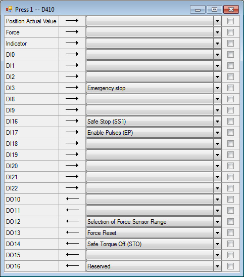
Figure 1: Window for associating variables to inputs/outputs of the D410-2
2.Select the input or output of the D410-2 to be associated to the user variable. To do this, click in the "CheckBox" of this physical input/output. (see figure 2 below).
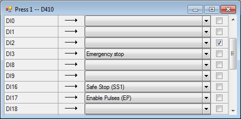
Figure 2: Selection of input 2 (DI2)
3.Use the drop-down list to select the variable to be associated to this input/output.
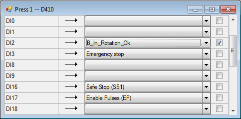
Figure 3: Selecting the variable to be associated
4.For the association to be effective, load the project into the D410-2 control unit .
Example of use: We want to check that the final insertion force of a part is greater than 65[N]. •If "Final Force" > 65[N] => a green lamp connected to the DO10 output of the D410-2 lights up. •If "Final Force" < 65[N] => a red lamp connected to the DO11 output of the D410-2 lights up. To do this, you must first associate two Boolean variables to the physical outputs DO10 and DO11. (See Figure 4)  Figure 4: Association of variables to the outputs of the D410-2 CPU (lamps can be connected to these outputs) Then, in a program (figure 5), you must test if the value of the final force is greater than 65[N], and depending on the result, set the "Insert OK" or "Error" variables to "1" to switch on the lamps. 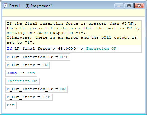 Figure 5: Example of a program testing whether the final force > 65[N] |
