
Presse universelle MecaMotion par 
"Stop on force" control instruction
Unlike the "stop on signal" instruction, which stops the axis as soon as a signal passes a certain threshold, the "stop on force" control is dedicated to stopping the axis in relation to the force, with a regulation of the feed velocity in order to have, a final force very close to the setpoint given.
The regulator incorporated in this control is of type "P" (proportional). With the gain adjustable directly in the instruction.
This regulator works as follows:
•Every 2[ms] the value of the force sensor is read and compared with the setpoint.
•As the difference between the setpoint and the measured force decreases, the axis velocity will decrease (proportionally) until it reaches the minimum velocity (parameter "minimal velocity").
The regulator will start to operate as soon as the axis reaches the working position. At this point, the velocity will decrease by "X"[%] of its previous velocity (parameter "working velocity [%]") and after that, the velocity will be regulated.
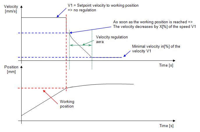
Figure 1: Graphical explanation of how the "stop on force" control works
Below is a list of the instruction's input and output parameters:
Parameter name |
Declaration |
Type of data |
Default value |
Description |
|---|---|---|---|---|
Working position [mm] |
Input |
LREAL |
0[mm] |
Position from which the feed velocity will first be reduced to X[%] of its initial value and then regulated |
Force setpoint [N] |
Input |
LREAL |
10[N] |
Force setpoint to be reached |
Velocity regulator gain [-] |
Input |
LREAL |
1 |
Proportional gain of the regulator. The higher this value, the faster the approach velocity will decrease. |
Minimal velocity [%] |
Input |
LREAL |
10[%] |
Minimum velocity that the regulation can reach, the velocity cannot go below this value. This one is given as a percentage of the initial axis velocity. |
Working velocity [%] |
Input |
LREAL |
50[%] |
Percentage decrease in velocity from the initial velocity when the working position is reached. |
Table 1: Summary of the different parameters of the instruction
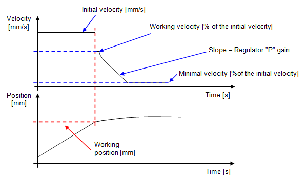

Figure 2: Programming window and graphic explanation
Below you will find the calculation of the working velocity, the initial velocity is equal to 10[mm/s].
•When switching to the working position, the axis velocity will change to:
Working velocity = 80[%] of 10[mm/s] = 8[mm/s] working velocity
•The controller can reduce the axis velocity to:
Minimum velocity = 2[%] of 10[mm/s] = 0.2[mm/s]
Example of use: We want to insert one part into another with a force of 150[N]. The final force must be as close as possible to the set point, which is why it is not possible to use the signal stop control, which is much less accurate. The gain, minimum velocity and working velocity parameters must be adjusted on test pieces, in order to be as precise as possible.  Figure 3: Graphical explanation of the application 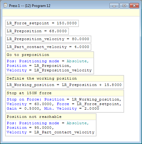 Figure 4: Programming a "stop on force" instruction |
